- 您现在的位置:买卖IC网 > Sheet目录342 > MCBSTM32EXL (Keil)BOARD EVALUATION FOR STM32F103ZE
�� �
�
�RM0008�
�24.3.5�
�SDA/SCL� line� control�
�Inter-integrated� circuit� (I� 2� C)� interface�
�●�
�If� clock� stretching� is� enabled:�
�–�
�–�
�Transmitter� mode:� If� TxE=1� and� BTF=1:� the� interface� holds� the� clock� line� low�
�before� transmission� to� wait� for� the� microcontroller� to� read� SR1� and� then� write� the�
�byte� in� the� Data� Register� (both� buffer� and� shift� register� are� empty).�
�Receiver� mode:� If� RxNE=1� and� BTF=1:� the� interface� holds� the� clock� line� low� after�
�reception� to� wait� for� the� microcontroller� to� read� SR1� and� then� read� the� byte� in� the�
�Data� Register� (both� buffer� and� shift� register� are� full).�
�●�
�If� clock� stretching� is� disabled� in� Slave� mode:�
�–�
�–�
�–�
�Overrun� Error� in� case� of� RxNE=1� and� no� read� of� DR� has� been� done� before� the�
�next� byte� is� received.� The� last� received� byte� is� lost.�
�Underrun� Error� in� case� TxE=1� and� no� write� into� DR� has� been� done� before� the� next�
�byte� must� be� transmitted.� The� same� byte� will� be� sent� again.�
�Write� Collision� not� managed.�
�24.3.6�
�SMBus�
�Introduction�
�The� System� Management� Bus� (SMBus)� is� a� two-wire� interface� through� which� various�
�devices� can� communicate� with� each� other� and� with� the� rest� of� the� system.� It� is� based� on� I� 2� C�
�principles� of� operation.� SMBus� provides� a� control� bus� for� system� and� power� management�
�related� tasks.� A� system� may� use� SMBus� to� pass� messages� to� and� from� devices� instead� of�
�toggling� individual� control� lines.�
�The� System� Management� Bus� Specification� refers� to� three� types� of� devices.� A� slave� is� a�
�device� that� is� receiving� or� responding� to� a� command.� A� master� is� a� device� that� issues�
�commands,� generates� the� clocks,� and� terminates� the� transfer.� A� host� is� a� specialized� master�
�that� provides� the� main� interface� to� the� system's� CPU.� A� host� must� be� a� master-slave� and�
�must� support� the� SMBus� host� notify� protocol.� Only� one� host� is� allowed� in� a� system.�
�Similarities� between� SMBus� and� I� 2� C�
�●�
�●�
�●�
�●�
�2� wire� bus� protocol� (1� Clk,� 1� Data)� +� SMBus� Alert� line� optional�
�Master-slave� communication,� Master� provides� clock�
�Multi� master� capability�
�SMBus� data� format� similar� to� I� 2� C� 7-bit� addressing� format� (� Figure� 231� ).�
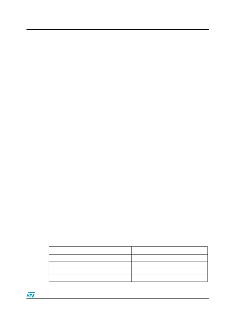
�Differences� between� SMBus� and� I� 2� C�
�The� following� table� describes� the� differences� between� SMBus� and� I� 2� C.�
�Table� 170.� SMBus� vs.� I� 2� C�
�SMBus�
�Max.� speed� 100� kHz�
�Min.� clock� speed� 10� kHz�
�35� ms� clock� low� timeout�
�Logic� levels� are� fixed�
�I� 2� C�
�Max.� speed� 400� kHz�
�No� minimum� clock� speed�
�No� timeout�
�Logic� levels� are� V� DD� dependent�
�Doc� ID� 13902� Rev� 9�
�635/995�
�发布紧急采购,3分钟左右您将得到回复。
相关PDF资料
MCBTMPM330
BOARD EVAL TOSHIBA TMPM330 SER
MCIMX25WPDKJ
KIT DEVELOPMENT WINCE IMX25
MCIMX53-START-R
KIT DEVELOPMENT I.MX53
MCM69C432TQ20
IC CAM 1MB 50MHZ 100LQFP
MCP1401T-E/OT
IC MOSFET DRVR INV 500MA SOT23-5
MCP1403T-E/MF
IC MOSFET DRIVER 4.5A DUAL 8DFN
MCP1406-E/SN
IC MOSFET DVR 6A 8SOIC
MCP14628T-E/MF
IC MOSFET DVR 2A SYNC BUCK 8-DFN
相关代理商/技术参数
MCBSTM32EXLU
功能描述:开发板和工具包 - ARM EVAL BOARD + ULINK2 FOR STM32F103ZG
RoHS:否 制造商:Arduino 产品:Development Boards 工具用于评估:ATSAM3X8EA-AU 核心:ARM Cortex M3 接口类型:DAC, ICSP, JTAG, UART, USB 工作电源电压:3.3 V
MCBSTM32EXLU-ED
制造商:ARM Ltd 功能描述:KEIL STM STM32EXL EVAL BOARD
MCBSTM32EXLUME
功能描述:开发板和工具包 - ARM EVAL BOARD + ULINKME FOR STM32F103ZG
RoHS:否 制造商:Arduino 产品:Development Boards 工具用于评估:ATSAM3X8EA-AU 核心:ARM Cortex M3 接口类型:DAC, ICSP, JTAG, UART, USB 工作电源电压:3.3 V
MCBSTM32F200
功能描述:开发板和工具包 - ARM EVAL BOARD FOR STM STM32F207IG
RoHS:否 制造商:Arduino 产品:Development Boards 工具用于评估:ATSAM3X8EA-AU 核心:ARM Cortex M3 接口类型:DAC, ICSP, JTAG, UART, USB 工作电源电压:3.3 V
MCBSTM32F200U
功能描述:开发板和工具包 - ARM EVAL BOARD FOR STM STM32F207IG + ULINK2
RoHS:否 制造商:Arduino 产品:Development Boards 工具用于评估:ATSAM3X8EA-AU 核心:ARM Cortex M3 接口类型:DAC, ICSP, JTAG, UART, USB 工作电源电压:3.3 V
MCBSTM32F200UME
功能描述:开发板和工具包 - ARM EVAL BOARD FOR STM STM32F207IG ULINK-ME
RoHS:否 制造商:Arduino 产品:Development Boards 工具用于评估:ATSAM3X8EA-AU 核心:ARM Cortex M3 接口类型:DAC, ICSP, JTAG, UART, USB 工作电源电压:3.3 V
MCBSTM32F200UME-ED
制造商:ARM Ltd 功能描述:KEIL STM32F207IG EVAL BOARD
MCBSTM32F400
功能描述:开发板和工具包 - ARM EVAL BOARD FOR STM STM32F407IG
RoHS:否 制造商:Arduino 产品:Development Boards 工具用于评估:ATSAM3X8EA-AU 核心:ARM Cortex M3 接口类型:DAC, ICSP, JTAG, UART, USB 工作电源电压:3.3 V